Oscilloscope


Oscilloscope Control Panel Overview


SCPI, Storage, and Generators Controls

|
|||
|---|---|---|---|
| Button | Function | Button | Function |

|
Open file explorer to load a file with extension .txt with SCPI scripts. | 
|
Begins the recording of SCPI commands based on the actions performed by the user on the oscilloscope interface. |

|
Ends SCPI command recording. | 
|
Saves the recorded SCPI script with the user defined name. |

|
Takes a screenshot and saves it on the internal storage or in external USB flash drive. |

|
It generates a file with a .csv extension with the wave information on the screen, it is saved in the internal storage or in an external USB flash drive. |

|
Displays the Oscilloscope configuration menu . | 
|
Changes the control panel to the Oscilloscope control panel. |

|
Changes the control panel to the arbitrary waveform generator control panel, the option is only available if the arbitrary waveform generator is selected from the main menu. | 
|
Changes the control panel to the radio frequency generator control panel, the option is only available if the radio frequency generator is selected from the main menu. |
System Panel
| System Panel | Button | Function | Button | Function |
|---|---|---|---|---|

|

|
Resets the Oscilloscope to their default values (Table -) |

|
Evaluates all input waveforms and find the optimum conditions for displaying the waveform. |

|
Starts/stops the oscilloscope’s waveforms acquisition. | 
|
Causes the oscilloscope to make a single acquisition when the next trigger event occurs. |
Trigger Panel
| Trigger Panel | Button | Function | Button | Function |
|---|---|---|---|---|

|

|
Activates the function to adjust the trigger level. |

|
Activates the function to adjust the offset level of the trigger. |

|
Changes the trigger slope between positive, negative and both, each time the button is pressed, the selected option is highlighted in green below the button. | 
|
Changes the trigger mode between auto and normal, each time the button is pressed the selected option is highlighted in green below the button. | |

|
Changes the trigger source between the four channels or line, each time the button is pressed the selected option is highlighted in green below the button. |
System and Measure Panel
| System and Measure Panel | Button | Function | Button | Function |
|---|---|---|---|---|

|

|
Displays the menu to perform the parameter measurement in any of the active channels. The available measurements are: maximum voltage, minimum voltage, peak voltage, peak to peak voltage, RMS voltage, period and frequency. | 
|
It displays the menu for the selection of the acquisition mode , the available modes are: normal, minimum, maximum, minimum-maximum and random. |

|
Displays the display configuration menu , through which the intensity and view of the grid can be adjusted. | 
|
some text here | |

|
some text here | 
|
Displays the menu to configure the number of layers of the display , the available options are: 8K, 16K, 32K, 64K, 128K, 256K, ∞. |
Cursors and intensity Panel
| Cursors and intensity Panel | Button | Function | Button | Function |
|---|---|---|---|---|

|

|
Displays the horizontal and vertical cursors menu (figure -). | 
|
some text here |
Scale selection Panel
| Scale Selection Panel | Button | Function | Button | Function |
|---|---|---|---|---|

|

|
Changes the scale setting to vertical scale (volts / div). | 
|
Changes the adjustable scale to the horizontal scale (S / div). |

|
Changes the adjustable scale to trigger options (level, offset, holdoff). |
Universal Knob and Arrows
| Universal Knob and Arrows | Button | Function | Button | Function |
|---|---|---|---|---|

|

|
Increase or decrease any active numeric value on screen. | 
|
Both have the same function than the universal knob, Increase or decrease any active numeric value on screen. |

|
Change the granularity steps between fine (yellow button) and coarse (gray button). |
Scale, Offset and Zero Panel
| Scale, Offset and Zero Panel | Button | Function | Button | Function |
|---|---|---|---|---|

|

|
Activates the scale configuration (vertical, horizontal, or trigger), using the knob and arrows depending of scale selected in the scale selection panel #UM_OSC_Overview__ssp | 
|
Activates the offset configuration (vertical, horizontal or trigger) using the knob and arrows, depending of scale selected in the scale selection panel #UM_OSC_Overview__ssp |

|
Returns the offset, holdoff and level values to zero. |
Impedance and Coupling Selection

|
Changes the coupling of each channel between AC / DC and the impedance between Hi-z / 50Ω. | |||
XY and Math Mode Selection
| XY and Math Mode Selection | Button | Function | Button | Function |
|---|---|---|---|---|

|

|
Activates the XY mode display and menu on the oscilloscope. | 
|
Displays the menu of mathematical operations between each channel. |
Channel Buttons
| Channel Buttons | Button | Function | Button | Function |
|---|---|---|---|---|

|

|
Turns on, off and / or selects channel 1 output. | 
|
Turns on, off and / or selects channel 2 output. |

|
Turns on, off and / or selects channel 3 output. | 
|
Turns on, off and / or selects channel 4 output. |
Oscilloscope Functions


To Set Channel
Press ![]() ,
, ![]() ,
, ![]() or
or ![]() to activate the on-screen display of the
waveform acquired by the specified channel, or to change the selected acquisition
channel. When the button is fully colored
to activate the on-screen display of the
waveform acquired by the specified channel, or to change the selected acquisition
channel. When the button is fully colored ![]() it means that the
on-screen display of the waveform acquired by that channel is activated and the
channel is selected to change its parameters, when the button only has a colored
stripe below
it means that the
on-screen display of the waveform acquired by that channel is activated and the
channel is selected to change its parameters, when the button only has a colored
stripe below ![]() , it means that the
on-screen display of The waveform acquired by that channel is activated but it is
not selected to be able to change its parameters, when the button is completely gray
, it means that the
on-screen display of The waveform acquired by that channel is activated but it is
not selected to be able to change its parameters, when the button is completely gray
![]() , it means that the
display of the data acquired by that channel is off and it is also not selected for
parameter editing.
, it means that the
display of the data acquired by that channel is off and it is also not selected for
parameter editing.
 |
|
Set the Vertical Scale
To change the amplitude scale (volts / div),
press the button ![]() in the menu below the
knob, then press the button
in the menu below the
knob, then press the button ![]() in the scale selection
panel that is to the left of the knob. Next, the amplitude scale can be changed
using the knob or the arrows, the steps with which the amplitude changes will depend
on the granularity value (fine or coarse), the current value will appear in the
vertical channel indicator on the screen.
in the scale selection
panel that is to the left of the knob. Next, the amplitude scale can be changed
using the knob or the arrows, the steps with which the amplitude changes will depend
on the granularity value (fine or coarse), the current value will appear in the
vertical channel indicator on the screen.
Set the Horizontal Scale
To change the time scale (sec / div), press
the button ![]() in the menu below the
knob, then press the button
in the menu below the
knob, then press the button ![]() in the scale selection
panel that is to the left of the knob. Next, the time scale can be changed using the
knob or the arrows, the steps with which the time changes will depend on the
granularity value (fine or coarse), the current value will appear in the time base
indicator on the screen.
in the scale selection
panel that is to the left of the knob. Next, the time scale can be changed using the
knob or the arrows, the steps with which the time changes will depend on the
granularity value (fine or coarse), the current value will appear in the time base
indicator on the screen.
Set the Trigger Scale
To change the trigger values (trigger level,
trigger offset or trigger holdoff), press the button ![]() in the menu below the
knob, then press the button
in the menu below the
knob, then press the button ![]() in the scale selection
panel that is to the left of the knob. Next the selected trigger variable can be
changed using the knob or the arrows, the steps with which changes will depend on
the granularity value (fine or coarse), the current value will appear in the trigger
holdoff, trigger offset or trigger level indicator on the screen.
in the scale selection
panel that is to the left of the knob. Next the selected trigger variable can be
changed using the knob or the arrows, the steps with which changes will depend on
the granularity value (fine or coarse), the current value will appear in the trigger
holdoff, trigger offset or trigger level indicator on the screen.
To Set the Trigger
 |
|
Trigger Slope
To change the trigger slope value, it is only
necessary to press the button ![]() inside the trigger panel, each time the
button is pressed the selected value is underlined in green
inside the trigger panel, each time the
button is pressed the selected value is underlined in green ![]() . Selectable values are: positive,
negative, and both.
. Selectable values are: positive,
negative, and both.
Trigger Mode
To change the trigger mode value, it is only
necessary to press the button ![]() inside the trigger panel, each time the
button is pressed the selected value is underlined in green
inside the trigger panel, each time the
button is pressed the selected value is underlined in green ![]() . Selectable values are: auto and
normal.
. Selectable values are: auto and
normal.
Trigger Source
To change the trigger source value, it is only
necessary to press the button ![]() inside the trigger panel, each time the
button is pressed the selected value is underlined in green
inside the trigger panel, each time the
button is pressed the selected value is underlined in green ![]() . Selectable values are: Channel 1,
channel 2, channel 3, channel 4 and line.
. Selectable values are: Channel 1,
channel 2, channel 3, channel 4 and line.
Trigger Level
To change the trigger level value, press the
button ![]() on the scale selection
panel, then press the button
on the scale selection
panel, then press the button ![]() on the trigger panel, the value can be
changed using the knob or the arrows, the trigger level indicator on the screen will
go showing the current value and the trigger level cursor will change position based
on the current value.
on the trigger panel, the value can be
changed using the knob or the arrows, the trigger level indicator on the screen will
go showing the current value and the trigger level cursor will change position based
on the current value.
Trigger Offset
To change the trigger offset value, press the
button ![]() on the scale selection
panel, then press the button
on the scale selection
panel, then press the button ![]() on the trigger panel, the value can be
changed using the knob or the arrows, the trigger offset indicator on the screen
will go showing the current value and the trigger offset cursor will change position
based on the current value.
on the trigger panel, the value can be
changed using the knob or the arrows, the trigger offset indicator on the screen
will go showing the current value and the trigger offset cursor will change position
based on the current value.
Trigger Holdoff
To change the trigger holdoff value, press the
button ![]() on the scale selection
panel, then press the button
on the scale selection
panel, then press the button ![]() on the trigger panel, the value can be
changed using the knob or the arrows, the trigger holdoff indicator on the screen
will go showing the current value.
on the trigger panel, the value can be
changed using the knob or the arrows, the trigger holdoff indicator on the screen
will go showing the current value.
To Set the offset
 |
|
To Make Measurements
 |
|
Measure Parameter Menu
 |
|
Measure Maximum Voltage
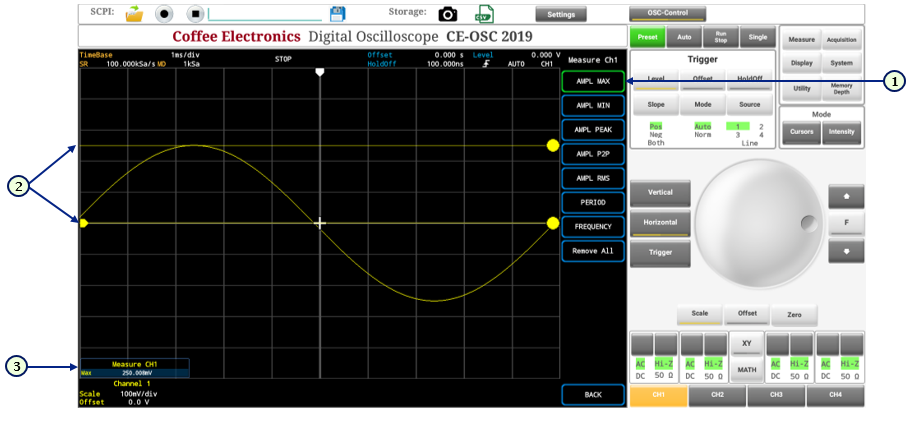 |
|
Measure Minimum Voltage
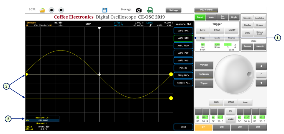 |
|
Measure Peak Voltage
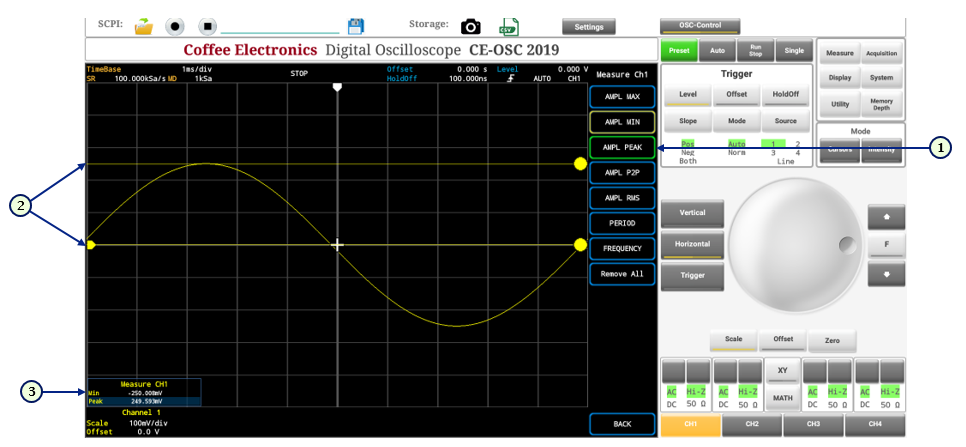 |
|
Measure Peak to Peak Voltage
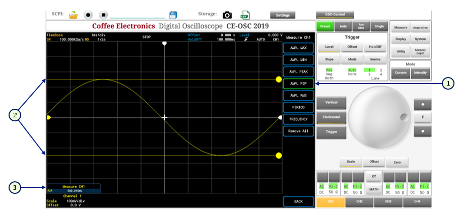 |
|
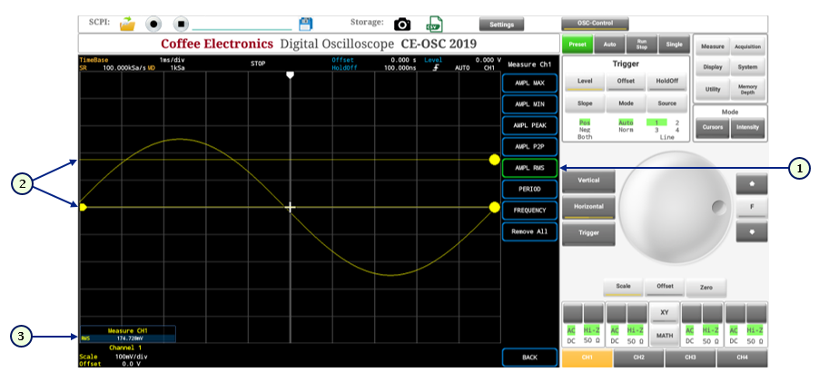
Measure RMS Voltage
 |
|
Measure Period
 |
|
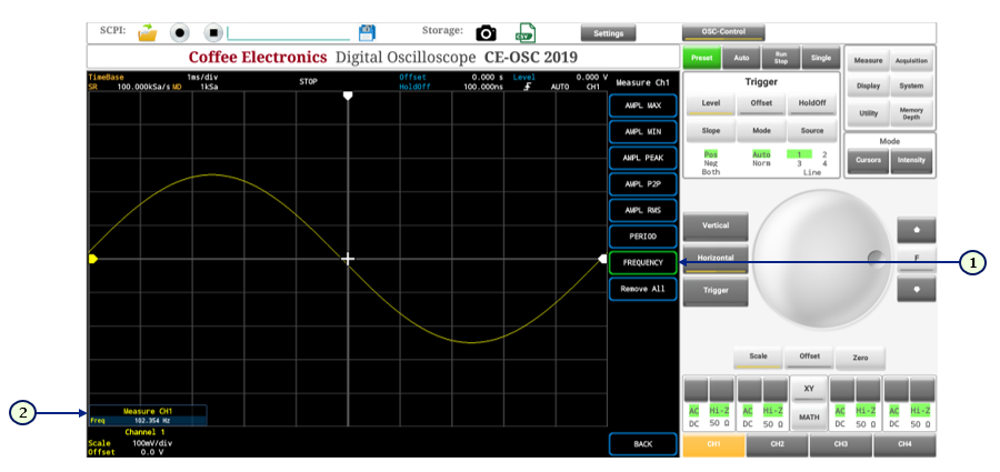
Measure Frequency
 |
|
To Activate Cursors
 |
|
Activate Horizontal Cursors
 |
|
Detailed Instructions
Horizontal cursor 1: To activate / deactivate the horizontal cursor 1 press the button
 in the horizontal cursors menu, when the
button turns green, it means that the cursor is
activated. When it turns blue it means it is disabled.
When cursor 1 is activated, it is displayed in red on
the screen. After being activated, its position can be
changed using the knob or arrows.
-
Horizontal cursor 2: To activate / deactivate the horizontal cursor 2 press the button
 in the horizontal cursors menu, when the
button turns green, it means that the cursor is
activated. When it turns blue it means it is disabled.
When cursor 2 is activated, it is displayed in green on
the screen. After being activated, its position can be
changed using the knob or arrows.
Horizontal cursor 3: To activate / deactivate the horizontal cursor 3 press the button
 in the horizontal cursors menu, when the
button turns green, it means that the cursor is
activated. When it turns blue it means it is disabled.
When cursor 3 is activated, it is displayed in magenta
on the screen. After being activated, its position can
be changed using the knob or arrows.
Horizontal cursor 4: To activate / deactivate the horizontal cursor 4 press the button
 in the horizontal cursors menu, when the
button turns green, it means that the cursor is
activated. When it turns blue it means it is disabled.
When cursor 4 is activated, it is displayed in blue on
the screen. After being activated, its position can be
changed using the knob or arrows.
Horizontal cursor delta: The horizontal delta cursor shows the time difference between its own position and the position of the selected cursor. To activate / deactivate the horizontal cursor delta press the button
 in the horizontal cursors menu, when the
button turns green, it means that the cursor is
activated. When it turns blue it means it is disabled.
When cursor delta is activated, it changes the color
depending on the cursor that you have as reference
measure. For example, in the following figure, the delta
cursor has the horizontal cursor 3 as measurement
reference, therefore, its color will be the same than
the cursor 3 (magenta). If the reference cursor changes
to horizontal cursor 1, the color of the delta cursor
would change to red, which is the color of cursor 1.
After the horizontal delta cursor is activated, its
position can be changed using the knob or the arrows.

Multiple horizontal cursors: Multiple horizontal cursors can be shown on the screen at the same time, in this case the menu button corresponding to the selected cursor will appear in green and the others that are activated on the screen, but not selected will appear in yellow. In the following figure the five cursors are activated on the screen, but the selected cursor is the delta cursor, because its button appears in green and the rest in yellow, like delta cursor is the selected one, it can be moved in position using knob and arrows.

Activate Vertical Cursors
 |
|
Detailed Instructions
vertical cursor 1: To activate / deactivate the vertical cursor 1 press the button
 in the vertical cursors menu, when the
button turns green, it means that the cursor is
activated. When it turns blue it means it is disabled.
When cursor 1 is activated, it is displayed in red on
the screen. After being activated, its position can be
changed using the knob or arrows.
vertical cursor 2: To activate / deactivate the vertical cursor 2 press the button
 in the vertical cursors menu, when the
button turns green, it means that the cursor is
activated. When it turns blue it means it is disabled.
When cursor 2 is activated, it is displayed in green on
the screen. After being activated, its position can be
changed using the knob or arrows.
vertical cursor 3: To activate / deactivate the vertical cursor 3 press the button
 in the vertical cursors menu, when the
button turns green, it means that the cursor is
activated. When it turns blue it means it is disabled.
When cursor 3 is activated, it is displayed in magenta
on the screen. After being activated, its position can
be changed using the knob or arrows.
Vertical Cursor 4: To activate / deactivate the vertical cursor 4 press the button
 in the vertical cursors menu, when the
button turns green, it means that the cursor is
activated. When it turns blue it means it is disabled.
When cursor 4 is activated, it is displayed in blue on
the screen. After being activated, its position can be
changed using the knob or arrows.
Vertical Cursor Delta: The vertical delta cursor shows the time difference between its own position and the position of the selected cursor. To activate / deactivate the vertical cursor delta press the button
 in the vertical cursors menu, when the
button turns green, it means that the cursor is
activated. When it turns blue it means it is disabled.
When cursor delta is activated, it changes the color
depending on the cursor that you have as reference
measure. For example, in the following figure, the delta
cursor has the vertical cursor 2 as measurement
reference, therefore, its color will be the same than
the cursor 2 (green). If the reference cursor changes to
vertical cursor 1, the color of the delta cursor would
change to red, which is the color of cursor 1. After the
vertical delta cursor is activated, its position can be
changed using the knob or the arrows.
Multiple Vertical Cursors: Multiple vertical cursors can be shown on the screen at the same time, in this case the menu button corresponding to the selected cursor will appear in green and the others that are activated on the screen, but not selected will appear in yellow. In the following figure the five cursors are activated on the screen, but the selected cursor is the delta cursor, because its button appears in green and the rest in yellow, like cursor 3 is the selected one, it can be moved in position using knob and arrows.

To Set Acquisition Mode
 |
|
- Normal Acquisition Mode:
To activate acquisition in normal mode, press the button
 in the
acquisition mode menu.
 - Minimum Acquisition Mode:
To activate acquisition in minimum mode, press the button
 in the
acquisition mode menu.
 - Maximum Acquisition Mode:
To activate acquisition in maximum mode, press the button
 in the
acquisition mode menu.
 - Minimum/Maximum Acquisition Mode:
To activate acquisition in minimum/maximum mode, press the button
 in the
acquisition mode menu.
 - Random Acquisition Mode:
To activate acquisition in random mode, press the button
 in the
acquisition mode menu.
To Set the XY Mode
To Math Mode
To Set Channel Coupling
 |
|
To Set Channel Impedance
 |
|
To Set Zero
 |
|
To Set Arbitrary Waveform Generator Panel
When the arbitrary waveform generator is
selected from the main menu, upon entering the oscilloscope a tab will appear at the
top of the control panel ![]() . If the arbitrary
waveform generator is not selected in the main menu, the tab
. If the arbitrary
waveform generator is not selected in the main menu, the tab ![]() will not appear on the
oscilloscope.
will not appear on the
oscilloscope.
 |
|
To Set RF Generator Panel
When the RF generator is selected from the
main menu, upon entering the oscilloscope a tab will appear at the top of the
control panel ![]() . If the RF generator is
not selected in the main menu, the tab
. If the RF generator is
not selected in the main menu, the tab ![]() will not appear on the
oscilloscope.
will not appear on the
oscilloscope.
 |
|
Preset the Oscilloscope
The preset returns all the oscilloscope
variables to their default values. Which are listed in next table. To make the
preset on the oscilloscope, press the button ![]() in the system panel. All the
oscilloscope variables will automatically change to their default value.
in the system panel. All the
oscilloscope variables will automatically change to their default value.
| Group | Variable | Value |
|---|---|---|
| Time Base | 1 mS/div | |
| Trigger | Slope | Positive |
| Mode | Auto | |
| Source | Channel 1 | |
| Level | 0 V | |
| Offset | 0 V | |
| Holdoff | 100nS | |
| Granularity | Coarse | |
| Cursors | Horizontal 1 | Status: OFF; Position: 0 S |
| Horizontal 2 | Status: OFF; Position: 0 S | |
| Horizontal 3 | Status: OFF; Position: 0 S | |
| Horizontal 4 | Status: OFF; Position: 0 S | |
| Horizontal delta | Status: OFF; Position: 0 S | |
| Vertical 1 | Status: OFF; Position: 0 V | |
| Vertical 2 | Status: OFF; Position: 0 V | |
| Vertical 3 | Status: OFF; Position: 0 V | |
| Vertical 4 | Status: OFF; Position: 0 V | |
| Vertical delta | Status: OFF; Position: 0 V | |
| Acquisition | Mode | MIN/MAX |
| Display | Type | Vectors |
| Memory Depth | Depth: 16 K | |
| XY state | OFF |
| Variable | Value | |||
|---|---|---|---|---|
| Channel 3 | Channel 2 | Channel 3 | Channel 4 | |
| Channel State | ON | ON | ON | ON |
| Channel Coupling | AC | AC | AC | AC |
| Channel Impedance | Hi - Z | Hi - Z | Hi - Z | Hi - Z |
| Vertical Scale | 100 mV/div | 100 mV/div | 100 mV/div | 100 mV/div |
| Vertical Offset | 0 V | 0 V | 0 V | 0 V |
| Status of all Measures | OFF | OFF | OFF | OFF |
Save and Load States
Implemented, but pending restructuring.
Taking and Saving a Screenshot
 |
|
Save a .csv File
The .csv file option allows you to generate and save a file with a .csv extension where each of the time samples and their corresponding amplitude value are stored for each of the channels that are turned on at the time of generating the file. It also saves the value of the time base and the trigger position. This file can be opened and graphed in programs like Microsoft Excel and Matlab.
 |
|
Oscilloscope’s General Settings (Language, Brightness)

